
The User interface
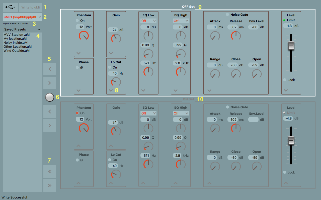
Main feature: uMi is capable of storing two presets in its hardware memory. Switching between the two presets is achieved by pressing the hardware push button.
The selected OFF and ON -presets (9)/(10) are indicated with the LED placed in the button’s cap.
(1) Write to uMi indicator/button will blink when one of the settings is altered and the preset is not written to the hardware memory. By clicking Write to uMi the two onscreen presets are saved to the hardware memory.
(2) The number and unique serial number of the connected uMi: when two or more uMi’s are connected, the user can select the uMi device via the drop-down menu.
(3) Indicator of the selected Sample rate and bit depth, when the uMi is active.
(4) A list of the saved presets in the memory of the computer. The user can save and recall an unlimited number of presets in the system.
(5) Save and Recall buttons for the presets. By clicking the Left arrow, the active preset will be saved locally. By pressing the Right arrow, the locally saved preset will be activated on screen. The user has to make sure the preset will be saved to the uMi’s memory by clicking (1).
(6) Indicator/button to switch between the OFF and ON presets. This UI button is the equivalent of the hardware button located on the uMi itself.
(7) Both presets can be saved and loaded simultaneously. The user can save preset OFF and ON in one file locally. A double preset can be loaded simultaneously to the onscreen presets. The user has to make sure the preset will be saved to the uMi’s memory by clicking (1).
(8) Just one single setting can be sent / copied to, or from, preset OFF and ON. If needed the user can send just one set value of one of the knobs, the rest of the values will remain unchanged.
(9) (10) The OFF and ON preset names.
Channel-Strip
The uMi hardware architecture permits the use of several audio Algorithms, accelerated in the DSP functionality of the interface itself.
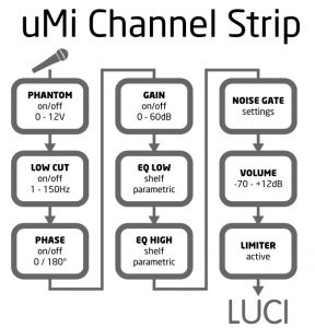
Phantom
The Phantom power can be switched On/Off.
The output level can be set between 0 and 12V.
Low Cut
When activated, the input signal passes a low cut (high-pass) filter. This second order low cut filter has a cutoff frequency that can be set between 1Hz and 150Hz and has a slope of 12dB per octave.
Low Cut is used to remove rumble and unwanted low frequencies from the input signal.
Phase
The phase of the incoming signal can be inverted by activating this function.
Phase inversion can help reduce phase cancellations when more than one microphone is used to record the same source.
Gain
The Gain (amplification) of the incoming microphone signal can be set between 0 and 60dB.
In the most cases the microphone signal will have to be amplified; the Gain function is specially developed for this.
EQ Low
The incoming signal can be equalized with a LOW filter Equalizer. There are two options included: Shelf and Parametric equalization.
Shelf Equalizer
The Gain can be set between -20 and +20dB.
The cutoff frequency can be set between 50 and 6400 Hz.
Parametric Equalizer
The Gain can be set between -20 and +20dB.
The Q factor can be set between 0.5 and 50.
The cutoff frequency can be set between 50 and 6400 Hz.
The EQ Low can be used to amplify / attenuate the low side of the audio spectrum to get a better balance between the sound frequencies. The EQ low is often used to bring brightness to the audio signal by boosting the low frequencies.
EQ High
The incoming signal can be equalized with a HIGH filter Equalizer. There are two options included: Shelf and Parametric equalization.
Shelf Equalizer
The Gain can be set between -20 and +20dB.
The cutoff frequency can be set between 0.5 and 16 kHz.
Parametric Equalizer
The Gain can be set between -20 and +20dB.
The Q factor can be set between 0.5 and 50.
The cutoff frequency can be set between 0.5 and 16 kHz.
The EQ High can be used to amplify/attenuate the high side of the audio spectrum to get a better balance between the sound frequencies. The EQ High is often used to soften harsh vocals and reduce noise in the recording / broadcast.
Noise Gate
The Noise Gate can be switched ON/OFF in the channel-strip altering the audio signal.
Imagine standing in front of a fence gate and whispering, “I want to come in.” Nothing happens. Then you yell, “I WANT TO COME IN” and this time the gate opens. The higher volume level is what opened the gate.
This functionality is useful in very noisy environments.
Attack: controls the speed of the gate opening. Can be set between 0 and 200ms.
Release: controls the speed of the gate closing. Can be set between 0 and 1000ms.
Range: the amount of decibels reduction to the signal once the gate is closed. Can be set between 0 and 100dB.
Close: at which audible level the gate closes. Can be set between -60 and 0dB.
Open: at which audible level the gate opens after being closed. Can be set between -60 and 0dB.
Volume
The volume of the outgoing audio signal can be set with this fader.
The volume fader can be set between -70 and +12dB.
If you switch on Lock, the level of your device is locked and cannot be changed by your OS. This is to prevent unwanted level changes when you use the uMi in different Applications or OS’s
Limiter
The Limiter s always activated and attenuates the audio signal when it exceeds 0dB.
The Limiter is used to prevent digital distortion in the recording / broadcast when the output level exceeds 0dB.